DIY (de)soldering station with heat gun for $25
1.Intro
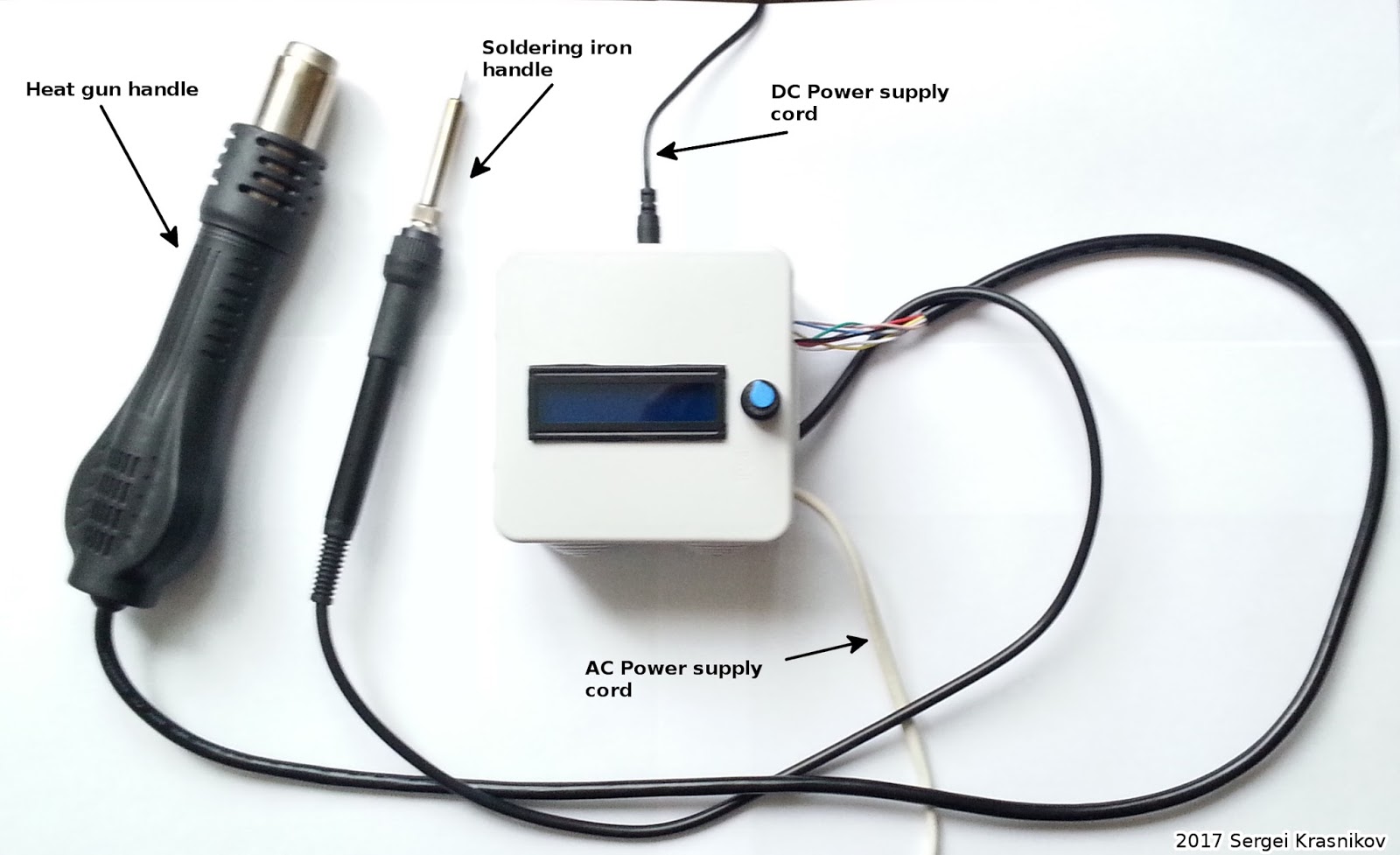
Pic.overall view
I explain how to make and calibrate a simple soldering station. The soldering station is controlled by an arduino.
Main features
1) the soldering station's display showing both temperatures for the soldering iron and the heat gun also showing the fan's speed of the heat gun;
2) separate temperature control for the soldering iron and the heat gun;
(thermostats are implemented by using on-off controller);3) control of the fan's speed of the heat gun.

Fig. structural block diagram of the soldering station

Pic. inside the box

Pic. Display menu
Pressing the knob (encoder) selects the active menu item (the soldering iron's temp, the heat gun's temp, and the fan's speed). Turning the knob changes the item's value.
2. Role of breakout board / Schematic
This is a board designed for controlling a soldering iron and a heat gun.
This board is helpful for connecting digital systems (like a 5V microcontroller or an Arduino) to a high-voltage system.
OpAmps are used for temperature measurements. They are implemented into the circuit as a pair of non-inverting amplifiers, which transform the thermocouples' voltages to the appropriate range for the arduino's ADC. Power MOSFETs are used as power switches. When the first MOSFET turns on/off, high current starts/stops to flow through the soldering iron's heating element. The second MOSFET is used for controlling speed of the heat gun's fan. A TRIAC with a zero-crossing driver are used for delivering high AC voltage to the heat gun's heating element.

Fig. Schematic of the breakout board

Fig. PCB layout
The schematics and PCB layout can be downloaded here (EagleCAD' files)
3.Wiring diagrams

Pic. heat gun (hot air gun) pinout
Check out my video where I explained how to find out the pinout for the heat gun handle.

Pic. soldering iron handle pinout
Check out my video where I explained how to find out the pinout for the soldering iron handle.

Pic. encoder & display

Pic. breakout board
4. Program (a sketch for arduino)
Here you can find firmware for the arduino.
5. Calibration

Pic. Calibration
if a thermocouple is located near a heating element, it produces a voltage proportional to a temperature of the heating element (sensitivity is about 41uV/°C for a type K thermocouple). However, in practice we want to convert this voltage to the actual temperature of the soldering iron's tip that we use. So we need to calibrate our soldering iron station. This means we need to find a function that maps the given voltage to the temperature. Our arduino already maps the thermocouple's voltage to some number by design. Why? See the schematics and the wiring diagrams. We use the opamp to amplify the thermocople's voltage then we use the arduino's ADC to convert it to a number.
To calibrate the soldering station I use an external thermocouple with a multimeter that can measure temperatures. (Although other devices could be used)
The procedure consists of the following steps.
1. Rotate the soldering station's encoder to set a temperature value. Wait until the actual temperature stabilizes (the actual temperature = the set temperature). Let Xi be the set temperature.
2. Using an external thermocouple measure the temperature of the soldering iron's tip. Let Yi be the temperature measured by an external device.
3. Using different set temperatures repeat 1-2 steps a few times . i=1,2,...n
4. Now we have the set of points (X1,Y1),(X2,Y2),....,(Xn,Yn)
5. Find a function that maps Xi to Yi for all i=1,..,n.
If we have only 2 points (X1,Y1),(X2,Y2), then we can draw the line (Y=a*X+b) between the points. This line will be the solution to the problem. If we have more than 2 points, we should use the method of least squares.
6. Use the function to convert ADC's numbers to actual temperatures.
Example.
We've followed the steps 1-4.
Now we have the following table
| i | Xi set temperature | Yi temperature measured by an external device |
|---|---|---|
| 1 | 40 | 52 |
| 2 | 80 | 95 |
| 3 | 100 | 125 |
| 4 | 160 | 195 |
We can use an online service to find the function.
Let's open wolframalpha.com. Then we should type the string "linear fit {40,52},{80,95},{100,125},{160,195}" in the edit box.
And here we are!

The solution for our problem is y= 1.202 x+2.56.
I used this function in the arduino's sketch to convert ADC's numbers to actual
temperatures.

Hints
1)Do the calibration in the vicinity of your working temperature.
2)If you don't have an external device to measure temperatures you can calibrate anyway (although with low resolution). For example you can use the melting point of a flux (rosin flux), a solder (for example, 60/40 Sn-Pb - 183°C), the boiling point of water as reference points.
3)The soldering iron should be recalibrated after changing the iron, or replacing the heating element or tip.
4)The tip temperature will vary according to the shape of the tip. A less accurate method involves adjusting the temperature control knob according to the adjustment value for each tip.
6. Misc (some thoughts)
I don't like to drill extra holes in a fiberglass copper board. So I used SMD components but you can use full size components (or even assemble the station on a breadboard).
Instead of the MOSFETs you can use power BJT (Darlington transistors) for the same voltage range. But keep in mind then you probably should use additional heat-sinks for BJT to dissipate heat.
I recommend to use an encoder having threads and a fitted nut to easily mount it on the soldering station' front panel.
Use 1nF capacitors for the encoder's pins to filtrate switching noise (otherwise you should modify firmware to treat debouncing...).
There is a correlation between input DC Voltage and heating speed of the soldering iron. So if you want DC Voltage to be at 24V you should make additional DC 5V..15V for the arduino. Why? Because the arduino's linear regulator (in my case it was a LM1117) doesn't tolerate 24V. (For example, It can be done by using a DC-DC buck (or SEPIC) converter.)
Always cool down the hot air gun with the internal fan before turn it off. Its heating element will last longer.
For safety purposes, you should use a fuse in series with the heat gun's heating element.
7. Components
table of the components
| devices | links |
|---|---|
| Arduino nano v3 clone (ATmega328P/ch340) | ebay aliexpress |
| IRFZ44N (MOSFET) * | ebay aliexpress |
| MOC3043 (TRIAC driver) * | ebay aliexpress |
| BT139 (TRIAC) * | ebay aliexpress |
| LM358D (Opamp) | ebay aliexpress |
| Hot air gun handle | ebay aliexpress |
| Soldering iron handle (Hakko 907 clone) | ebay aliexpress |
| Soldering tips (900M series) | ebay aliexpress |
| Encoder (having threads and a fitted nut) | ebay aliexpress |
| LCD 2x16 Display (Hitachi HD44780 clone) | ebay aliexpress |
* Be careful with power devices. I had some unpleasant experience with broken MOSFETs (probably they were refurbished or counterfeit) which I bought from a high rated ebay seller... maybe it's better to buy power devices from a trusted (re)seller or at your local trusted store where you can easily replace/exchange them. There are some other reports.
other devices
| device | links |
|---|---|
| External device to measure temperature | ebay aliexpress |
| DC-DC SEPIC (buck/boost) converter | ebay aliexpress |
8. Demo
Links
[1] This project on GitHub
[2] If you are interested in making a PID controller for this soldering station,
you should read this article: "PID without a PhD" by Tim Wescott
[3]Youtube videos:
Soldering iron handle pinout
Heat gun handle pinout
How to make rework station/hot air gun for $15
Do you have any video tutorials to better explain what should be done? I'm a little lost in this article.
ReplyDeleteCould you specify which part of my article you're referring to? And what should I clarify?
DeleteMore specifically the part of the PCB where there are some SMD resistors where I have not seen which part has well specified values
DeleteThis comment has been removed by the author.
DeleteThis comment has been removed by the author.
DeleteI would like to thank you for the efforts you have made in writing this article. I am hoping the same best work from you in the future as well.. jbc nase 1b nano soldering station
DeleteHow can single rotary encoder control soldering iron, rework station element & fan
DeleteHello. I tryed to look at the datasheet on how to remake the circuit for 110V but I could not find the information. Can you be more specific? I'm interested on doing one.
ReplyDeleteMany thanks
Hi. Thanks for asking. I've corrected this in the article. The changes are not needed. MOC3043 will work with 110VAC.
DeleteGreat Article Looking forward to getting the parts ! I was going to only have the heat gun. I noticed you had another video - using pre-made parts would it be easier to use that guide and add a arduino and screen (i have some experience doing this) or simply remove anything above related to the soldering iron.
ReplyDeleteНе подскажите, почему у меня в других скетчах постоянно на экране полоса, и только с этим кодом все нормально?
ReplyDeleteМожете сделать подключение экрана по i2c?
ReplyDeleteУ меня сейчас нет дисплея, работающего через i2c. Думаю, подключить такой дисплей просто. Надо найти библиотеку для ардуино, которая позволяет работать с таким дисплеем. Затем подключить дисплей к адрдуино, для нано к A4,A5(SDA,SCL), эти пины как раз будут свободны. Затем в скетче заменить пару строк на эквивалентные функции новой библиотеки, где включается сама библиотека, где инициализируется, затем заменить функции, которые осуществляют вывод на экран.
DeleteПонятно. Жаль я не разбираюсь в программировании. А по подключению там действительно все предельно просто.
DeleteThis comment has been removed by the author.
Delete#include <LiquidCrystal_I2C.h // add library LiquidCrystal_I2C_V112
DeleteLiquidCrystal_I2C lcd(0x3F, 16, 2);// i2c scan tape your adres 0x3F, 0x27 ...
add in voide setup
lcd.init();
lcd.backlight();
hi,
ReplyDeletei have a question, with your setup whats the power consumption from the wall to get the heat gun to 400c; i bought a heating gun handle with 70 ohm resistance; and if i give it a full 220v the handle get sherry red and extremely hot and start to melt! the thermocouple goes up near 1000c!; the most it accept without damage is 90volts which gave me about 500c from the handle thermocouple and 400c read out using the multimeter thermocouple; 90v and 70ohm equals 115watts!, so for me to get the heat gun to give me 400+c temp i only need 120watts!, i don't get it doesn't it suppose to draw close to 700watts like the 858D+ hot air rework station that this handle is supposedly for?
thanks
In this device, on-off controller is implemented. This means that if the actual temperature is lower than the set temperature, then the controller turns the heater on, otherwise the controller turns the heater off. So your heater won't overheat. In other words, the controller automatically regulates the power that delivered to the heater.
Deletehi again, i see, so in the already made units like the Youyue 858D they use the same concept; instead of stepping down the voltage to adjust the temperature they use on-off controller and always apply the full 220v, that will explain why its rated at 700watts, thanks again i appreciate your help.
Deletemay i know the model or link for the breakboard please. and do you have clear instruction of installation from breakboard to finish in a video will be better.
ReplyDeleteHi! I made the breakout board at my home. It's not difficult. You just need one-side copper board and a few chemical components from a drug store/grocery store. There are many recipes, I used hydrogen peroxide[3%,100mL], citric acid[crystallized, 20-30gram] and salt(5gram, NaCl) as a catalyst. You can see the process of making a PCB here https://www.youtube.com/watch?v=p9Umk5aG8Y4 or here https://www.youtube.com/watch?v=q6iu8Fe8UOY
DeleteThe 24v or 12v Dc is for power the Hot gun , but what is the difference if i power 12v or 24v???. The temperature ?? The speed of the fan?? I don't known the voltaje of the pins to control the Hot gun. Thank you.
ReplyDelete12..24V(DC) for the soldering iron's heating element, the heatgun's fan;
Delete5V..15V(DC) for arduino;
110-240V(AC) the heatgun's heating element.
---
The speed of the fan and the heating rate(speed) depend on the input voltage.
hi, can you explain the R14 resistor on lcd schematics on pin 15.
ReplyDeletethanks
Hi, this resistor limits the current which flows into the LEDs for the display backlight. Thus, if you change the resistor value, you will change the brightness. Start with 220..270 ohms. (Some sellers sell the displays with preinstalled resisors for backlights. You can check this by measuring resistance between A (Anode) and PIN15, K (Cathode) and PIN16. See Pic. encoder & display)
DeleteHi, Might it be easier to use a small potmeter with a resistor for R6 to calibrate or in the output of the Opamp by changing soldertips?
ReplyDeleteSo you do'nt need a computer to change the data
Willij
I have moc3021 and bt16-600b triac is it ok to use this part for your project,or i want to use special zero cross opto moc 3043 like you used in your circuit.
ReplyDeleteIf you use a TRIAC driver without zero-crossing, you will get a switching noise in your power line. This could affect other electrical devices in your home. I think that BTA16-600 is OK. Recommended devices: BT136..BT139, MOC3041, MOC3042, MOC3043. Please, be aware that different MOC304X use different LED trigger currents. So you might need to change the original schematic for your device (check datasheets).
Deletei am unable to find this parts moc 3043 and bt 139 in my country plz suggest other components..
ReplyDeleteHi, I'm trying to modify the project to have only with the heat gun.
ReplyDeleteFor the LCD I have an 1.8" inch 128x160 TFT LCD Shield Module, an AC 85-265V to DC 24V Switching Power Supply for the fan, and the DC-DC converter for the 5V to the Nano.
Could you suggest me how to modify the schematic and what parts can I exclude/change? (I can't find BT139 and LM358D).
Thanks!
then you don't need IC1A (1st opamp) and Q1 (1st MOSFET).
DeleteYou can buy LM358D on ebay or aliexpress. Also If you have an unused OpAmp, there is a proper way to connect it. https://e2e.ti.com/blogs_/archives/b/thesignal/archive/2012/11/27/the-unused-op-amp-what-to-do
Other recommended devices: BT136..BT139, MOC3041, MOC3042, MOC3043. Please, be aware that different MOC304X use different LED trigger currents. So you might need to change the original schematic for your device (check datasheets).
Thanks for the tips!
DeleteReviewing the PCB layout I noticed that IC1A is connected with the heat gun thermocouple, and IC1B with the iron's. A typo?
DeleteYes, you are right.
Deleteplz tell me resistor required for MOC3041M led triggring.
ReplyDeleteI am using MOC3041M @ BTA16-600b Triac.
also tell me what resistors are reqd to trigger triac ..
I need sam thing
Delete510 ohm
DeleteA good blog is a lot of educational issues. It's a nice blog. I think that this blog has a lot of educational issues. Thanks for blog. Beauty Tips
ReplyDeleteIs it possible to buy the breakout board from you? as a kit or as only pcb? :-) it would be awesome
ReplyDeleteNice project. I've ordered the parts and see how it goes.
ReplyDeleteThe Eagle files have some minor ERC errors though... nothing major. Maybe you could fix them for others?
Hi, nice project here! I might build one just like it! But could you tell me how many Amerps I could have? I have a colder station now with 72W. Is this stronger or no?
ReplyDeleteThank you alot!
soldering iron : about 15..25W (~15V*15V/15[Ohm] ), heatgun : 800..1000W (~240V*240V/60[Ohm])
Deletehey i have some issues with this project i replace the poamp with Lm358N and my readings for soldering iron are 255 deg for room temp
ReplyDeleteDid you calibrate your soldering station?
DeleteHi Sergei,
ReplyDeletenice simple project you made there, found it on youtube, thanks for sharing. I want to use three potentiometers intstead of the one encoder, changing the code is not that problem, if you like you can have it when I'm done and maybe make it better, but your schematics are hard to understand because of missing description to where which pins go, could you please add this to the schematics? And the amplifying part, does it amplify the thermistor value up to exact 5V?
Thank You and greetz,
Wilson
Hi! Please, feel free to share a link to your project in the comments.
Delete1) [about the pins]. Please, see the figure "Wiring diagram: breakout board". I marked all the pins over there. A0,A1,D8,D9 and etc... are the standard notations for the Arduino (nano) pins.
2) [about amplifying part] Actually, in this project, the amplification part designed for thermocouple sensors - not for thermistors. But you can easily change the schematics/circuit for a thermistor. Check my video where I explain how to do it @ 11:32 https://youtu.be/pG0xtk9URAI?t=11m32s
Thanks a lot.
ReplyDeleteI need to wait for parts to make sure my code works, ordered in China (I'm from Germany), so maybe I'm gonna post it with a "Happy new Year" :)
1) Have overseen that picture... sorry.
2) Sorry, I was misstyping, I ment thermocouple. But is your op-amp circuit set to the min-max temp of the heating element/s to 0-5V input Voltage, so 0-450(?) degree Celsius equals 0-1023? Or just to max possible value of the thermocouple/s to max input value?
If I understand your question correctly, you're asking about how temperature is mapped to OpAmps' output voltage and then to a number.
Delete1) The OpAmps are implemented into the circuit as a pair of non-inverting amplifiers. This means that the voltage gain A = 1 + Rf/R2 = 1 + 6K6/75 = 89. Thus, Vout/Vin = 89.
2)The sensitivity is about 41uV/°C for a type K thermocouple. Therefore, if the temperature range is [0..450]°C then the thermocouple gives the following voltage range = [0..450]°C*41uV/°C = [0..18.45]mV
3) At the OpAmp output we have [0..18.45]mV * 89 = [0..1.64]V
4) Arduino' ADC transforms this voltage range into [0..1.64]V * 1023 / 5V = [0..336]
The formula is as follows
X = temp[°C]*41u[V/°C]* 89* 1023 / 5[V]
For example, without the calibration, you should expect
a)at room temp = 25°C -> X = 19
b)at the melting point of the solder = 183°C -> X = 137
Please, keep in mind these are just rough estimates.
Hi,
Deletewow, thanks so much, I thought I start to annoy you because you gave already in the video a lot of info, but I still did not understand it. Now I got it, yipee :)
Thank you Sergei!
I just read your article and found it very helpful for those who are looking to buy the soldering iron at an affordable cost. You are doing a great job but what about those who don't know much about soldering irons. Well, if you are a newbie and don't know where to find the best one then it is recommended to take a look at this list of soldering irons. I bet you will find the best one for your needs on this link.
ReplyDeleteHai, nice site you have here! Keep up the excellent work!
ReplyDeleteElectronic waste disposal hyderabad, India
Nice project. Let me get some things straight please.
ReplyDelete1). From the YouTube video and from comments there (and here) I am assuming the Arduino gets 15V from outside power supply into VIN pin and outputs 5V for the rest (LM358 and MOC3043) and the LCD. I need this so I can draw a complete circuit diagram as this looks to me is bits and pieces. I will draw it myself, of course.
2). Does the heater and the soldering iron work at the same time or do they work separately?
3). Is it me or does the temperature raise seems very slow? Like 2-3 minutes in the YouTube video.
Thanks again.
Hello, i want to use your schematic, but i just have MOC4031, can you help me, what should i change/add??And if i use DC 24V 1A what should i do??if i have buck/boost converter, where can i place??I confused to try, because my budget is very low..Thank you
ReplyDeleteHi,very good project. I have ordered the parts from China end I wait...
ReplyDeleteDoes the project have auto timer off?
If not, is it possible to update the code?
Не планируете ли Вы реализовать возможности как в:
ReplyDelete"Lukey 868, 702 and 898 soldering stations have reed switch, which turns on when you place the hot air gun on the stand. Hot air gun is cooled to 50 º C and after that it shuts down. The station goes into standby mode. When you take the hot air gun off the stand, it turns on and resumes working with the last saved settings."
Было бы очень удобно ползоватся.
Собрал себе устройство, заработало сразу, большое спосибо.
sir im just asking if you have time to make a t12 soldering iron with hot air gun. what i mean just like this but instead of 907 soldering iron. you will use t12 soldering iron
ReplyDeleteHi,
ReplyDeletegoing to buy parts to make this.
i dont understand what power source is needed, i can see at it receives mains power (220v ac) i guess i need a 24v dc power source as well, how many amps ?
thanks
Thanks for A LOT of useful information. I need help choosing a soldering iron for soft soldering of charms and jewelry. I've gone through 3 models and seven tips now....the soldering tips are disintegrating on me! I don't understand why. Is it because I'm useing cheap models? 25w, 45w and 60? I thought maybe it was the chemical flux vs. rosin flux. Or is it the corrosive sal ammoniac? Then I read maybe it's the tips...they must be of ironclad.
ReplyDeleteI'm lost. Can you help?
Hello!
ReplyDeleteShort question: I ordered the parts, and have everything ready now. I am just confused about the MOSFETs. In your parts list, you name the IRFZ44N, while in the PCB diagram, you use the IRF520. Also, the diagram says B138, but on your picture, you use the B139 TRIAC. Are those parts interchangeable?
Thanks a ot for the great project!
Hi! These devices on my list of parts that I used in the actual project. The diagrams show devices with the same pinout, although they also should work.
DeleteThanks for the super fast reply. I finally soldered everything together and was quite amazed, that it worked right away. One Problem I face, though, is that the resistance in the Thermocouple of my Solder Iron is nor 5 but 50 Ohms. I'll try to replace R7 (75 Ohms) by a smaller one, 25 or 30 Ohms, I guess that should do the trick and yield more precise values, than this super noise stuff I am getting at the moment.
DeleteI'll put here some images once everything is going fine.
Thanks so much for the great instructions!
This comment has been removed by the author.
ReplyDeleteMen, you article is awesome!! thanks so much, i'm a software developer so i took your project and made seriuos improvements, i kept the hardware the same but i added a max6675 thermocoupler please try me version at
ReplyDeletehttps://github.com/danidip/Arduino, inside station folder you'll find the project itself, then in libraries folder some things needed to make it work, i added PID, EEPROM memory to save settings and some safety features, i didn't used soldering iron, just the heat gun, so i put a precompiler variable to discard the iron, feel free to ask me if you're lost!
Keep up the good work!
regards from Argentina
Hello my friend.
Deletecan you share the connection diagram of this project
Vesbuci31@gmail.com bu mailden ulaş arkadaşım ne lazımsa yollayım sana
DeleteThis comment has been removed by the author.
DeleteHola, estoy interesado me podrías compartir el diagrama de antemano muchas gracias
DeleteHey there :) how would you do it if your soldering iron has a thermistor already built in but only has a 3.5mm jack? how would you wire it?
ReplyDeleteI think you have the same issue as I have. Took some time for me to realize, that what I have there is a thermistor and no thermocouple. I worked out the following plan: According to what I read, the resistance of the thermistor varies between 50 ohm at ambient temperature and 200 ohm at 400°C.
Deletehttps://www.hackster.io/sfrwmaker/soldering-iron-controller-for-hakko-907-v-2-fc75d7
I want to use one digital Pin at HIGH, providing 40 mA at 5V, Meaning, that a resistor of 125 Ohms would completely suck up the voltage. So to "map" the voltage drop between 0-5 V, the resistance at 400°C e.g. must not exceed 125 Ohm.
I figured, that adding a 200 ohm resistor in series to the thermocouple will yield 100 ohm resistance at 400°C (200 ohm thermistor) and 40 ohm at ambient temperature (50 ohm thermistor). The voltage measured after the thermistor with the 200 ohm resistor in series would therefore yield 3.2 V at ambient temperature and 1 V at 400°C.
This voltage will be read by an analog pin and mapped to... something. it could be mapped to 20-400 (according to the temperature at the iron) and used directly for the feedback, when adjusting and keeping the temperature.
Let me know if I overlooked something critical. I'm no electrician, but biologist :D
In my other video, I demonstrated how to replace a thermocouple with a thermistor. The idea behind such a modification is shown here https://youtu.be/pG0xtk9URAI?t=691
DeleteMy PCB in Diptrace.
ReplyDeletehttps://www.dropbox.com/sh/8dfcyk46l65hve3/AAD1vEvm8-830sby1fK1w_d6a?dl=0
What are component names and values on pcb?? e.g.:C1,C2,C3,C4,U1,R11
DeleteSorry! The circuit is full of errors! Do not use this circuit!
DeleteAll OK with PCB.Open file with DIpTrace, double click on component and you see values.Some photos and video.
Deletehttps://www.dropbox.com/sh/oc14wu8vz0l0y79/AAAVoXIFRDdnqQNMCPcAbucsa?dl=0
(an amateur must be more modest ;)
Please give me C4 parameter specs
Deletehello is the what are this ceramic capacitor on the encoder? Can you give details?
ReplyDelete"""It was really insightful. Thanks for the info.
ReplyDeleteWanna have more contents from you. Cheers”"""
Also, You can Check best soldering gun kit here
Hello Sergei,
ReplyDeleteawesome circuit and very impressive, one problem I face is my measured teamprature is always showing 2, I verified connections and mine is a termocouple with 3 ohms resistance, the moment I increase the temp to 10c it's heats and becomes red..pls suggest what to do
You should test the devices separately.
Delete1. The thermocouple (of the soldering iron handle). Use a multimeter to confirm that the thermocouple works correctly. (Check this video https://www.youtube.com/watch?v=aVkXNvVu7EQ )
Keep in mind there are different iron handles with a ceramic heating element (a thermoresistor and a ceramic heater). My other video covers this case
https://www.youtube.com/watch?v=pG0xtk9URAI
2. The OpAmps. Instead of the thermocoupe, you could connect the input (+) port of the Opamp to 0V then to 5V and see if there are any changes on the display (Keep in mind If you have an unused OpAmp, there is a proper way to connect it. https://e2e.ti.com/blogs_/archives/b/thesignal/archive/2012/11/27/the-unused-op-amp-what-to-do )
typically your thermcouple connect wrong way, it has polarity positive and negative to output sensor voltage.
DeleteHello Sergei,
ReplyDeleteThank you so much for the reply, i am not using a soldering iron and only using the Hot gun handle (https://www.aliexpress.com/item/New-Hot-Air-Gun-Desoldering-Heat-Gun-Handle-for-858-858D-898D-852D-Soldering-Station/32397591094.html). I followed your video to get the pin outs and my heat element has 70ohms and Thermocouple has 3ohms. And I am using new opamps, i even tried to check with other one and same situation.
What I understand from my analysis so far is there are two issues
1. for some reason my thermocouple is not able to send the temp with reference volts , i will try your recommendation for verifying the opamps.
2. If i understand the circuit operation correctly the logic behind is that whatever the desired temp, the circuit switches on the heater till it reaches the required temp and shuts off once the temp is acquired.for me the the heater cut's off when desired is less than or equal to actual temp on the screen but the moment i turn the know to next level the heater and the air gun iron becomes hot red, now i am not sure would that happen in a default situation even if the heater is getting 220v handle should not go red??
thank you once again
I just read your article and found it very informative but still it is very complicated and time consuming to build a home made soldering station. Well, if you are looking to buy the best one for your needs at an affordable cost then it is recommended to take a look at this list of soldering irons.
DeleteI bet you will find the best one for your needs on this link.
switch thermcouple both lead conection, before opamp get negative sensor voltage
Deletenegative sensor voltage means controller never reach control status
DeleteThis comment has been removed by the author.
ReplyDeleteHello Sergei,
ReplyDeleteThe issue is resolved, it was happening because of not using soldering iron. I filled the post for unused opamp and then thermocouple stared reflecting the temp. Calibrated it and now all works perfectly..one last question for my knowledge, in the code what does ? And : do?
That sounds like the ternary operator. It's sort of an if / else statement. It works like this: If whatever comes before ? is true then use the value between the ? and the : else use the value after the : So if X is true then (X ? A : B) evaluates to A otherwise it evaluates to B.
DeleteThank you AI
DeleteAnd many thanks again for a great project it works flawlessly....
ReplyDeleteHi Sergei,
ReplyDeleteThank you to share this amazing project! I did it and works almost perfect.
On your software version, I got negative numbers to temperature on display; apart of this, everything works relly well.
Kregards,
AH
Very nice project, I'm just seeking around how to replace my cheap ZD-98 :) definitely will go this way. And as I happy owner of 858D heat gun as well, maybe I'll built it into that case.
ReplyDeleteHello Sergei,
ReplyDeleteI done all the circuit as you said. But i cant control the fan speed and the soldering iron thermo pin, they start working when i power on the station. I re-builded 3 times the circuit and i have the same error. I just replace the mosfet but nothing changes. i have recheck the program, but i dont found any error. can you help me?
Hi! There are many reasons why this does not work. You should break the problem down into smaller ones. Then solve the smaller problems. First, I suggest you to test your Arduino and MOSFETs. You should assemble a simple circuit to test them according to this schematic https://drive.google.com/file/d/1sDOcbRmwG6ytP7xY_lEyhioV8v86gON4/view?usp=sharing . If everything works well, you should see 1 second blinking.
DeleteBlink example https://www.arduino.cc/en/Tutorial/Blink
Deletehow to implement reed switch?
ReplyDeleteIt's enjoyable to learn more and more from your blog. Thanks for sharing.
ReplyDeletesoldering station
hello, you give me an idea to made my own rework station, i just need to read temps from the chip and feedback to the pid contrller, i just need a better transcient. Do you have any advice for arduino yo manage de temperature ramps?
ReplyDeleteMOC3043 can it be used at 220v?
ReplyDeleteI saw in the 115v datashet
thank you
Help.. Help..Help..
ReplyDeleteI've build this setup everything works well except temperature readings in Soldering & Hot Gun. With Connection & Without connection values are in High Level ( S=1,2 & S=850-900) It is variable so fast.If I increase temperature by heating values not gonna change. Please help me.
Help.. Help..Help..
ReplyDeleteI've build this setup everything works well except temperature readings in Soldering & Hot Gun. With Connection & Without connection values are in High Level ( S=1,2 & H=850-900) It is variable so fast.If I increase temperature by heating values not gonna change. I Used LM358N Please help me.
Hello dear friend Sergei Bravo for the work and thank you for sharing, I think this project will always be successful. Being an amateur I would have 2 questions please: 1) Can we replace the 2 75 ohm resistor of the LM358D with 2 100 ohm resistor (I haven't found a 75 ohm) 2) Is it possible to use a MAX6675 thermocouple module? Thank you in advance, wishing you very good health, long life full of happiness. Thank you.
ReplyDeleteThank you for sharing your work. I'm in the process of making this. PCB has been etched. Almost all components have been soldered. However, I have been unable to find the exact components listed in your post. I have got BTA12 for the triac. MOC3041 for the optocoupler which has 15ma trigger.
ReplyDeleteCan you tell me which resister values I need to change to accommodate these changes? I plan to publish by work here to help others.
I figured out the R9 value using ohms law
Delete5v arduino
15ma led trigger of MOC3041
Got 333.33 value
So I round off and use 330 ohm resistor for R9
Now trying to figure out the value of R4 and R5 but it looks complex
I am looking for a soldering station to repair mobile accessories and other small parts of watches and computer processors, It should be good in quality and economical as well,
ReplyDeletePlease guide me from the below link which should best suits me according to my requirements.
Thanks in advance.
soldering station price in pakistan
It's a great content ! desoldering station ! https://www.advancetech.co.in/products/goot-japan/soldering-desoldering-station/svs-800as
ReplyDeletearduino kod hata veriyor kodu gönderirmisiniz tekrar kontrol ederek teşekkür ederim.
ReplyDeleteПривет, Сергей!
ReplyDeleteМожно ли изменить программу так, чтобы при достижении заданного значения температуры не менять показания дисплея?
Так сильно раздражает глаз. К тому же, такая точность бессмысленна.
ReplyDeleteHey good information, can you tell me where can ibuy heat gun online pls suggest me
can you make good tutorial on calibration of this
ReplyDeleteHello, have a good time
ReplyDeleteI made this project and fortunately it works very well and efficiently and thank you for sharing it
But the problem is that when both the soldering iron and the heat gun start working together, the heat gun loses its accuracy and its temperature goes beyond the set value, while each of them individually has a very good accuracy. I would be grateful if you could help me to solve this problem. Thank you
I've build this setup everything works well except temperature readings in Soldering . With Connection & Without connection values are in High Level ( S=685 ) It is variable so fast.If I increase temperature by heating values not gonna change.When I connect the soldering iron, it starts from zero and quickly goes up to 685 degrees. It does not receive the set temperature. Please help me.
ReplyDeleteThanks and I have a keen offer you: How Long Does House Renovation Take house repair near me
ReplyDeleteThanks and that i have a swell provide: Whole House Renovation Checklist Pdf house renovation planner
ReplyDeleteHi, I don't know software program, I made this project hardware. I t works, but program can set temperature any high or low value, it is not reasonable. I hope the sketcher improvement made, let software set limited Temp within range, such as 0-450 C
ReplyDelete